
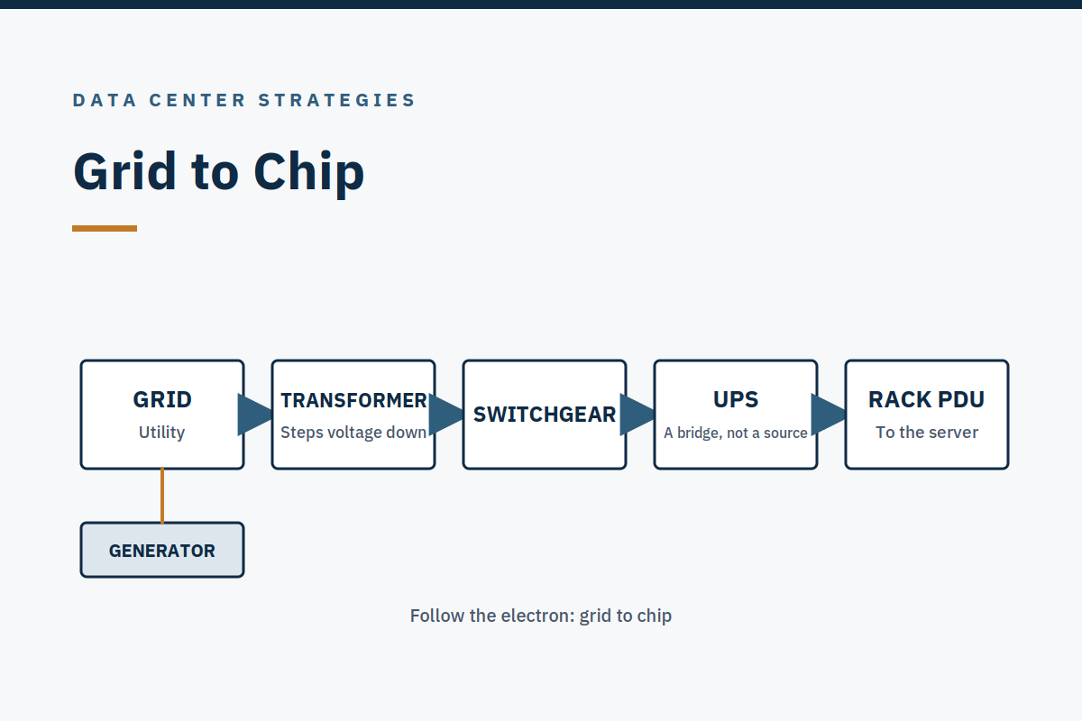
How does power get from the grid to a single chip? Follow one watt, and the answer is a chain of handoffs in a strict order, utility, substation and transformer, switchgear, generator bus via paralleling switchgear, automatic transfer switch, UPS and batteries with bypass, power distribution unit or remote power panel or busway, rack power distribution unit, server. At each handoff something can go wrong, and the operator's job is to know which handoffs matter most. Two of them do: the transfer switch to the UPS, and the UPS to the rack.
This article traces the path, names what can go wrong at each step, and explains why the mechanical loads branch off before the UPS.
Utility, substation, transformer
Electricity arrives from the grid, usually at medium or high voltage, and is stepped down through substations and transformers until it reaches the servers. The utility feed is the first single point of failure to understand: a campus may have one utility feed or two, from the same substation or from different ones, and the difference matters more than the number of generators downstream. Two feeds from the same substation share the substation's failures. The operator should know, for their own site, where the feeds come from and what they share, on the single-line diagram for this building.
Transformers step the voltage down in stages. Each stage is a handoff, and each handoff has its own protection: breakers that open on fault, relays that sense abnormal current, and the physical separation that keeps a fault in one part of the path from taking the rest with it. The single-line diagram is the map of this path, and it is one of the documents the turnover package must contain as installed, not as designed, because the two are never identical, and an operator working from the design drawing is working from a building that does not exist.
Switchgear and the generator bus
From the transformer, power passes through switchgear: the breakers, busbars, and protection that route power and isolate faults. The generator bus sits here, connected through paralleling switchgear that lets multiple generators run together and share the load. Generators stand by for a utility failure, and the paralleling switchgear is what turns several individual generators into one usable source.
The order matters, and it is the order most often misremembered: generators and the automatic transfer switch sit upstream of the UPS, and the UPS never feeds the generator. Power flows from the utility or the generator, through the transfer switch, to the UPS, and then to the load. A drawing that shows it the other way round is wrong, and a mental model that has it the other way round will mislead an operator at exactly the moment they need it most, during a transfer, under alarm, at 3 a.m.
The automatic transfer switch
The automatic transfer switch, ATS, is the device that senses the loss of utility power and transfers the load to the generator source. It is also the first of the two handoffs that matter most. The transfer is not instantaneous and it is not free: the ATS must sense the failure, confirm it is real rather than a momentary dip, start the generator, wait for the generator to reach rated voltage and frequency, and then transfer.
NFPA 110-2025 Type 10 systems must restore power at rated voltage and frequency at the load terminals within 10 seconds of utility failure, and the generator then accepts load in steps, block loading, rather than taking full load in 10 seconds (VERIFIED, NFPA 110; standards paywalled, no clause number cited).
The total time from utility failure to generator power is typically 2–10 seconds (ESTIMATE, consultant’s method: sensing and confirmation about 1–2 seconds, generator start and stabilization to rated voltage and frequency within the NFPA 110-2025 Type 10 10-second requirement, transfer itself under a second), dominated by sensing, start, and stabilization rather than by the transfer switch itself. This is our estimate, not a published market size. The generator being online and stable takes longer, typically 30–60 seconds.
What can go wrong at the ATS is the subject of Week 14 and Week 15, but the shape of it is worth stating here: a transfer switch that fails to transfer, transfers to a generator that is not ready, or transfers and then cannot transfer back.
The ATS is a single device in the path, and on many designs it is a single point of failure for the load it serves, which is why some designs use a static transfer switch, an STS, downstream, to give the load a second path. The question to ask of any ATS is "what happens if it does not, and what proves it?"
The UPS and its batteries
After the transfer switch comes the UPS, the uninterruptible power supply, with its batteries and its bypass. The UPS is a bridge, not a source: it carries the load for the seconds between losing utility power and the generators taking it, and it conditions the power while it does so. In a double-conversion UPS, the incoming alternating current is converted to direct current, which charges the batteries and feeds the inverter, which converts it back to alternating current for the load.
The load therefore never sees the raw utility supply; it sees the inverter's output, which is why a UPS also protects against sags, surges, and frequency variation.
Battery runtime in a conventional generator-backed design is commonly cited as 5–15 minutes, sufficient to bridge to generator start, and project-specific (VERIFIED, commonly cited range). Five to fifteen minutes is the time the generator has to start, stabilize, and accept the load, with margin. If the generator does not start, the batteries run out, and the load goes down. That is the whole of UPS runtime as an operational fact: it buys the generator time, and nothing else. Week 10 covers the UPS in full, including the two bypasses and the battery types.
The UPS also has a bypass, and the bypass is where the second critical handoff lives. The UPS-to-rack handoff is the point at which the load's power quality and redundancy are finally delivered, or not. Power quality itself, grounding, harmonics, and the problems you cannot see on a meter, is Week 16. Both power paths in a 2N design must reach the rack independently, and a single downstream panel shared by both paths defeats the redundancy of everything upstream of it. A spare UPS does not help if both paths share one panel.
That is the maintenance trap in its electrical form, and Week 12 takes it up directly.
Distribution: PDU, RPP, busway, rack PDU
From the UPS, power is distributed to the hall through power distribution units (PDUs), remote power panels (RPPs), or busway. The overhead or underfloor conductor system that runs down the row. Each is a different way of getting power from the UPS room to the rack, and each has its own failure modes: a PDU is a cabinet with breakers; a busway is a continuous conductor with tap-off points; an RPP is a panel that distributes to a group of racks.
The choice between them is a design decision, and the operator's job is to know which one their hall has, where its breakers are, and what load each circuit carries.
The last handoff is the rack PDU: the strip inside the rack that feeds the servers. A rack PDU may be metered, switched, or basic, and it may be fed from one power path or two. In a 2N rack, each server has two power supplies, one fed from each path, so that losing one path does not lose the server.
That is the redundancy the whole chain exists to deliver, and it only works if both paths are genuinely independent all the way from the utility to the rack. One shared panel, one shared breaker, one shared cable tray, and the independence is gone.
Why the mechanical loads branch off before the UPS
There is one more feature of the path that confuses new operators: the mechanical loads, chillers, pumps, fans, cooling towers, branch off before the UPS. They are not on UPS power. The reason is load and time. A UPS sized to carry the mechanical plant as well as the IT load would be enormous, and its batteries would be exhausted in minutes by the starting current of a chiller.
Instead, the mechanical plant is on generator-backed power: it loses power when the utility fails, and it comes back when the generators start, after the IT load has been protected by the UPS.
That ordering has an operational consequence that matters in a loss-of-cooling event. When utility power fails, the IT load stays up on the UPS and then on the generator, but the cooling plant is dark until the generators start and the chillers restart, and a chiller takes time to come back to full capacity. In a liquid-cooled hall, that gap is the reason UPS-backed technology-cooling-system pumps and CDU controls matter: they keep the coolant moving through the seconds when nothing else is.
The power path and the cooling path are coupled, and the coupling is in time, the seconds between the failure and the restart.
Reading the path on your own site
The exercise for a new operator is to trace this path on their own building, on the as-installed single-line diagram, from the utility entrance to one server in one rack. Mark each handoff. Ask, at each one, what happens if it fails, and what proves the answer. The two handoffs to spend the most time on are the ATS-to-UPS transfer and the UPS-to-rack delivery, because those are where the redundancy the design promises is either delivered or defeated. Everything upstream of them is the plant. Everything downstream is the load. The path between them is the operation.
Takeaway
Power flows in a strict order, utility, substation and transformer, switchgear, generator bus, automatic transfer switch, UPS and batteries, distribution, rack PDU, server, and the UPS never feeds the generator. The two handoffs that matter most are the ATS-to-UPS transfer and the UPS-to-rack delivery, because those are where redundancy is either delivered or defeated. Mechanical loads branch off before the UPS, which is why the seconds between a utility failure and the chillers restarting are the most consequential seconds in the building.
Further reading
- Transition to Operations guide, the guide to taking over a new data center.
- Case Study 1: Transition-to-Operations Readiness, what was missing at handover, and what the Handover Gate would have caught.
- Contact, start a conversation about a readiness review; a conversation, not a pitch.
Sources
- NFPA 110-2025 Type 10, 10-second restoration and block loading: NFPA 110-2025, Standard for Emergency and Standby Power Systems. The standard is paywalled; no clause number is cited.
- UPS runtime of 5–15 minutes: a commonly cited range; the figure varies by project.
- Total time from utility failure to generator power, typically 2–10 seconds: the author's estimate from stated inputs (sensing and confirmation about 1–2 seconds; generator start and stabilization within the NFPA 110-2025 Type 10 10-second requirement; transfer under a second), not a measured figure.
Published Saturday, October 24, 2026. By Scott Stillings. Scott spent more than twenty years in critical infrastructure operations, as a submarine reactor operator in the U.S. Navy, as a commercial nuclear operator and senior-reactor-operator-certified instructor, and as a critical operations manager for a large hyperscale data center campus. He is the author of Where AI Lives: Inside the Hyperscale Data Centers Powering the AI Boom (Inside Hyperscale).