
Summary: the short version. Liquid cooling does not change the operator's job description. It changes the clock, the fluids, and the failure modes. The job is still power in, heat out, nothing down, but in a cold-plate hall, chip thermal limits can be reached in seconds when circulation is lost, not minutes (VERIFIED, citing Uptime Institute). The coolant itself becomes a system to operate: composition, entrained air, stainless-steel passivation, and pressure can drift invisibly at commissioning and surface as damage months later (VERIFIED, ASHRAE TC 9.9, TCS Coolant Integrity and System Readiness Best Practices, May 2026).
And the remaining heat, commonly reported as roughly 20–30% of server heat, is still removed by air cooling in the hall (VERIFIED, range). This guide covers what actually changes for the operator: the two loops, the CDU, coolant integrity, loss of cooling, leak response, commissioning and turnover, and the efficiency numbers that are routinely misquoted.
Why liquid cooling, and why now?
The short answer is density. Average rack density was 27 kW, up from 16 kW the year before, and average facility size was approaching 38 MW, up from 32 MW (VERIFIED, AFCOM, State of the Data Center 2026, early 2026). Uptime's measure differs: average modal rack density surpassed 11 kW for the first time, with a growing number of operators reporting peak racks of 30 kW or above (VERIFIED, Uptime Institute, Global Data Center Survey 2026, July 2026). Modal density is not AFCOM's average density, so do not blend the two figures.
Either way, the direction is the same, and air cooling has a practical ceiling: air cooling struggles above roughly 30–40 kW per rack, and the same ceiling is about 40–50 kW as an airflow and physics limit, design-dependent (VERIFIED, range, design-dependent). Published air-cooling limits vary, routine air cooling up to about 12–15 kW per rack in one guide, 25–30 kW with good containment in another, so treat any single threshold as design-dependent, not a universal rule.
The AI rack makes the point concrete. The NVIDIA GB200 NVL72 is a rack-scale system integrating 72 Blackwell GPUs and 36 Grace CPUs in one rack-scale unit, requiring liquid cooling by design, at about 120 kW class (VERIFIED that it is about 120 kW class and liquid-cooled by design; the precise figure is UNVERIFIED, several trade sources say 132 kW, so do not quote a single precise figure without naming the source). At that density, there is no air-cooled version of the job.
The market direction is the same: Goldman Sachs forecast 76% of AI servers liquid-cooled by end-2026, up from 15% in 2024 (FORECAST, Goldman Sachs, forecast 2026, month/date unverified, via trade press), a forecast about the market, not a measurement of any site, and a direction indicator, not a site fact. That forecast date has now passed; whether it landed is checked in the annual review, not assumed here.
None of that changes what the operator does at 3 a.m. It changes what the operator must know before 3 a.m. arrives.
The two loops: TCS and facility water
The first discipline of liquid cooling is keeping two loops separate in every diagram and every sentence.
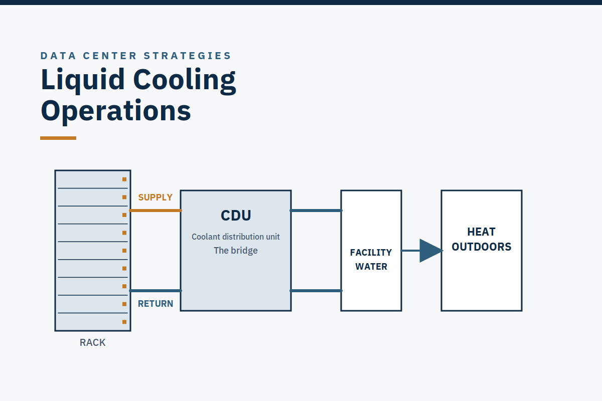
The TCS, Technology Cooling System, is the liquid loop serving IT directly: cold plates, manifolds, and the coolant that touches the servers. The CDU, Coolant Distribution Unit, is the bridge between the TCS and the facility water system. The facility water system is the building side: chillers, towers, dry coolers, and the outdoor heat rejection that already existed on air-cooled sites. The CDU transfers heat from the TCS to the facility water without mixing the two fluids, and the two fluids are different, with different chemistry, different treatment, and different consequences when they leak.
Why does the separation matter operationally? Because the two loops have different owners, different warranties, different failure modes, and different responses. A TCS problem is an IT problem: it touches the servers directly, and a loss of TCS flow is a loss of cooling for the chips it serves. A facility-water problem is a building problem. A CDU problem is the boundary between the two, and boundaries are where warranty disputes live (see failure mode F6 in the First 12 Months guide).
The warranty-responsibility matrix at handover must name the cooling vendor, the IT vendor, and the installer, and say who owns the CDU, who owns the TCS, and who owns the joint between them.
Keep the two loops separate in every diagram and every sentence. The day an operator says "the cooling loop" without saying which one is the day a MOP isolates the wrong loop.
What the operator actually does differently
Rounds: new readings, same discipline
Rounds on a liquid-cooled site add readings to a discipline that does not change. CDU flow, pressure, and conductivity. TCS supply and return temperatures. Filter restriction (differential pressure across filters). Coolant level and make-up. Leak-detection status. Pump status and run hours, per loop. The readings are new; the discipline is the same as it has always been: trend over alarm. A slow drift in conductivity or filter restriction that never crosses a threshold is still a failure in progress, and on a liquid-cooled site it is usually the first sign of the coolant-integrity drift covered below.
The clock: seconds, not minutes
This is the single largest operational change, and it is the one most often underestimated. In a cold-plate liquid-cooled hall, chip thermal limits can be reached in seconds at full load. Uptime puts it at "much less than a minute"; one cited case had CDU pump failure to throttling in as little as 23 seconds (VERIFIED for the seconds-scale claim; the 23-second figure is a single cited case and must not be generalized to every hall). Compare that with an air-cooled hall, where the air volume in the room buys minutes. The difference is not incremental.
It is the difference between a response measured in minutes and a response measured in seconds, and it is why the loss-of-cooling EOP's first stabilizing action is targeted inside 60 seconds of opening the document (Practitioner target. AI Data Center Guide template, not a standard).
Thermal mass does not rescue the clock. A closed-loop system of roughly 200,000 gallons bought the team in the author's account a minute or two of grace while chillers were restored, not the hours the volume might suggest (ESTIMATE, labeled as the author's experience, not a statistic). The mitigation is not volume. It is UPS-backed TCS pumps and CDU controls, so that a loss of utility power does not also become a loss of coolant circulation, and a drilled loss-of-cooling EOP.
See Case Study 5: The Cascading Loss of Cooling for the full account, and the SOP / MOP / EOP guide for how the EOP is written and drilled.
Continuous cooling: what the Tier really requires
Tier IV is the only Tier that requires continuous cooling; Uptime recommends continuous cooling above 4 kW/rack regardless of Tier (VERIFIED, Uptime Institute, Continuous Cooling paper). At AI densities, that recommendation covers every rack in the hall. Continuous cooling means the cooling does not stop, or does not stop for long enough to matter, through a power transfer, a component failure, or a maintenance event.
On a liquid-cooled site, that means UPS-backed pumps and CDU controls, redundant flow paths that are actually proved by fault injection, and a loss-of-cooling EOP that assumes the cooling will stop and says what to do in the first minute. If the design provides for load shed or load transfer on loss of cooling, the EOP says so and the operator drills it. If the design does not provide for it, the EOP says that too, honestly, and the gap is a handover finding, not a surprise.
The air that remains: 20–30% is still air-cooled
Direct-to-chip liquid cooling does not remove air cooling from the hall. The remaining heat, commonly reported as roughly 20–30% of server heat, from memory, drives, network cards, and fans, is still removed by air cooling in the hall (VERIFIED, range). Liquid share is typically 70–80% in earlier direct-to-chip designs, with platform figures labeled by platform; the Vera Rubin shipping product is 100% liquid-cooled with no fans. Do not quote a single fixed split.
The operational consequence is that the air-cooled systems do not go away: the CRAH units, the airflow management, the hot-aisle and cold-aisle discipline, and the room-level temperature monitoring all still matter, and they still need procedures, maintenance, and drills. A liquid-cooled hall that neglects its air side will lose servers to the 20–30% it forgot about, while the liquid side performs perfectly.
Coolant integrity: the failure mode you cannot see
ASHRAE TC 9.9 published the Technical Bulletin TCS Coolant Integrity and System Readiness Best Practices in May 2026. It catalogues four ways a direct-to-chip technology cooling system can drift invisibly at commissioning and surface as damage months later: coolant composition, entrained air, stainless-steel passivation, and pressure ratings (VERIFIED, ASHRAE TC 9.9, May 2026). Its opening warning is worth quoting in full: "It is too easy to violate direct-to-chip cooling system operational and warranty requirements." The bulletin is informational guidance; it does not supersede IT-equipment manufacturer requirements or local code.
Each of the four drift modes is invisible in the ordinary sense: the plant runs, the temperatures look normal, and the damage accumulates.
Coolant composition. The wrong mix, the wrong inhibitor concentration, or a mix that drifts as make-up water is added. The defense is a lab-verified coolant specification at turnover, composition, chemistry, conductivity, inhibitor, and sampling and lab verification on the watch schedule through the first year, trending conductivity, chemistry, pressure, flow, and filter restriction.
Entrained air. Air in the loop reduces heat transfer, causes pump cavitation, and creates corrosion sites. The defense is an air-management and degassing plan, proved at commissioning and maintained in operation, not assumed, because air enters a loop through maintenance, make-up, and any opening of the system.
Stainless-steel passivation. The protective oxide layer on stainless steel must be formed correctly (passivation) or the steel corrodes from the inside. The defense is passivation records at turnover, and a recognition that a passivation failure is not visible until the damage is done.
Pressure ratings. The loop must be proved against its pressure ratings, with hydrostatic evidence, because a TCS that is over-pressured, or under-pressured, which invites air ingress, is a leak or a corrosion event waiting for a date. The defense is pressure and hydrostatic evidence at turnover, and pressure trending in operation.
One more reported figure belongs here with its label intact. ASHRAE TC 9.9's 2024 resiliency bulletin reports that IT equipment makers have seen TCS temperature jumps of as much as 27 °C when CDU pumps changed over without active redundancy (REPORTED, secondary summary, ReliabilityEngine, 2026; re-check against the ASHRAE TC 9.9 bulletin before quoting the figure to a client). It is reported, not primary-verified, and it is included here because it states the operational point precisely: a CDU pump changeover without active redundancy is not a routine event.
It is a thermal event. Plan it as one, with a MOP, a back-out plan, and an operator watching the TCS supply temperature, not as a background switchover.
Loss of cooling: the EOP that matters most
Loss of cooling is the EOP that matters most on a liquid-cooled site, and it is the one most likely to have been written for an air-cooled hall and never rewritten. The air-cooled version assumes minutes. The liquid-cooled version has seconds. Three things must be true of it.
First, the first stabilizing action is inside 60 seconds of opening the document (Practitioner target. AI Data Center Guide template, not a standard). That target is demanding, and it is the right one, because the clock is seconds. If the EOP's first action cannot be done in 60 seconds, because it requires a phone call, a key, a second person, or a decision the operator has to make, the EOP is wrong, and the drill will prove it. Rewrite the EOP, not the drill result.
Second, the EOP is drilled as an injected-fault drill, not a tabletop. A tabletop is a discussion. A drill disconnects pumps, chillers, and air handlers to trigger authentic alarms. The readiness guidance says to regularly simulate every EOP scenario that way. For loss of cooling, the tabletop proves the operator knows the words. The drill proves the operator can do the first action in 60 seconds, under alarm, at 3 a.m.
Third, the EOP says what the design provides, and what it does not. If the design provides for load shed or load transfer, the EOP says how, and who decides. If it does not, the EOP says so, and the gap is recorded as a handover finding. An EOP that implies a capability the design does not have is worse than no EOP, because it will be followed, confidently, into a dead end.
The worked example is Case Study 5: The Cascading Loss of Cooling: a cascading loss of cooling over several hours, one pump kept running, recirculation plus a ~200,000-gallon loop buying a minute or two, one chiller then a second restored over several hours. The graphs are qualitative schematics with no percentage values and no clock times. Read it for the shape of a cascade and for the lesson that thermal mass is a buffer measured in minutes at full load, not a ride-through.
Leaks: a cooling event and a fire-protection event
A coolant leak is two events at once, and the operator must treat it as both. It is a cooling event: loss of fluid, loss of pressure, loss of heat transfer. And it is a fire-protection and containment event. The fluid has a type and a flammability, the leak has a location and a spread, and the containment in the aisle may obstruct sprinklers or gas suppression.
The leak EOP therefore has two halves, and the second half is the one most often missing: state the fluid type and its flammability, isolate the loop, contain the spill, and coordinate with fire protection and the authority having jurisdiction. Aisle containment that obstructs sprinklers or gas is a design coordination issue, and it is a handover finding if it has not been coordinated.
Leak detection must be layered and proved in the field. The commissioning and IST record shows it was proved, and the leak-response EOP has been drilled. That is Handover Gate check 25, and it is a red line if it is absent: no leak-response capability on a liquid-cooled site, no detection proven, no EOP, no isolation procedure, no coolant spill kit or containment, forces "Do not sign" for the affected scope. The assessor reviews the record; he does not perform or witness the test.
Commissioning and turnover: what "ready" means on a liquid-cooled site
The Handover Gate applies in full to a liquid-cooled site, and three of its 27 checks are liquid-cooling-specific. They are worth listing together, because they are the checks a generic readiness review misses.
- Check 21: warranty-responsibility matrix signed by all parties, including the liquid-cooling boundary (cooling vendor vs IT vendor vs installer). A failure that sits between two vendors is the one that waits longest for a fix.
- Check 24: coolant specification lab-verified at turnover (composition, chemistry, conductivity, inhibitor, ASHRAE TC 9.9, May 2026).
- Check 25: leak-detection coverage, with the commissioning/IST record showing layered detection was proven in the field, and the leak-response EOP drilled.
Two further points belong at turnover. First, the common TCS supply temperature, flow, and pressure agreement, the shared operating envelope the cooling vendor, the IT vendor, and the operator all agree to, is held by the operator, not by any one vendor. When a failure sits on a boundary, the common agreement is the document that settles whose boundary it is. Second, ASHRAE liquid classes describe the warmest facility water the equipment accepts: W17, W27, W32, W40, W45, and W+ (above 45 °C) (VERIFIED, ASHRAE TC 9.9).
Equipment rated for warmer water (for example W32/W40) can often be cooled by towers or dry coolers alone for much of the year, with chillers needed less often. Know the liquid class of the equipment you operate, because it decides what the facility water system has to deliver, and what happens when it cannot.
Efficiency: PUE, WUE, and the numbers that are routinely misquoted
Liquid cooling is routinely sold on efficiency, and the efficiency numbers are routinely misquoted. Three rules keep the operator honest.
PUE = total facility energy ÷ IT energy. A PUE must be stated with its measurement boundary (what is counted), period (annual average, not a snapshot), IT load (utilization), and climate. A PUE quoted without those four is not a number, it is a slogan (VERIFIED, definition and method, The Green Grid / ISO/IEC 30134-2:2026). The industry fleet average PUE is 1.52 (Uptime 2026 survey); modern air-cooled hyperscale runs about 1.1–1.2; Google fleet 1.09–1.10 in 2024 (VERIFIED, Uptime Institute Global Data Center Survey 2026; Google fleet figure 2024).
The pair "legacy air-cooled 1.55–1.67, direct-to-chip liquid 1.10–1.20" is a Schneider Electric vendor comparison (July 2026) of legacy air against new liquid, not an air-versus-liquid verdict, never quote it as a site forecast saving. And no one in this guide promises a PUE figure: a PUE is a measurement of a specific site under specific conditions, not a guarantee a consultant can offer.
WUE = annual site water in liters ÷ annual IT energy in kWh. The Green Grid introduced it in March 2011; ISO/IEC 30134-9:2022 specifies WUE as a key performance indicator (VERIFIED). What counts is evaporation, blowdown, and drift, not closed-loop recirculation. Reported, climate-dependent WUE ranges (per source, not blended): a closed-loop or dry-cooler system about 0–0.1 L/kWh; adiabatic about 0.1–0.4 L/kWh (VERIFIED, ranges with attribution caveat). Evaporative cooling at about 1.8–1.9 L/kWh is widely repeated, but the sources found attribute it to EESI, not to a Uptime 2023 survey, do not cite it as Uptime's.
The EU adds a regulatory frame: on 21 September 2026 the European Commission adopted delegated regulation C(2026) 3472 creating a common Union rating scheme, an A–G class for energy efficiency (PUE, class A if PUE ≤ 1.15) and an A–G class for water efficiency (WUE, class A if WUE ≤ 0.1; class G above 1.0), with first labels due by 15 August 2027 and the act sent to the European Parliament and Council for a two-month scrutiny period (VERIFIED, European Commission, September 2026).
The European Parliament extended scrutiny on 6 October 2026; the exact end of the extended period is unconfirmed, about 21 November 2026. Entry into force is still to be confirmed, so re-check before citing it as in force.
Temperature envelopes are guidance, not setpoints. ASHRAE TC 9.9's recommended server-inlet air range for classes A1–A4 is 18–27 °C (64.4–80.6 °F); the allowable range is wider (for example A1 15–32 °C, A4 5–45 °C), and operating at the warm end of the allowable range is a design and reliability choice, not a free gain. For high-density air-cooled class H1, the recommended range is narrower, 18–22 °C. Humidity: dew point −9 to 15 °C, maximum 70% RH (VERIFIED, ASHRAE TC 9.9, Thermal Guidelines for Data Processing Environments).
A liquid-cooled hall still has an air side, and the air side still has an envelope. Raising a setpoint because the liquid side is performing well is a change-control decision, not an optimization freebie, and it goes through the same review, approval, and return-to-service check as any other setpoint change.
The first year on a liquid-cooled site
The first year on a liquid-cooled site is the first year in the First 12 Months guide, with four failure modes that are liquid-specific or liquid-amplified: F4 (cascading loss of cooling, seconds-scale, see above), F8 (coolant integrity drift, the ASHRAE four), F6 (warranty-boundary disputes, the CDU boundary), and F3 (chiller tuning and calibration drift, control sequences never exercised at real load).
Case Study 2: Post-Turnover Operational Watch covers the year's pattern, and Case Study 3: The Silent Compressor Failures is a reminder that the facility-water side of a liquid-cooled site has its own silent failures, and that the only clue may be a small change in a trended temperature.
When to ask for help
Liquid cooling appears in all three of Data Center Strategies' offers, because it cuts across all three: the Transition-to-Operations Readiness offer includes a liquid-cooling readiness check at its Large tier (anchor $28,000, 4–6 weeks, see the Transition to Operations guide for the full tier table). The Post-Turnover Operational Watch: 90-day / 12-month covers coolant sampling and lab verification on the watch schedule, seasonal-transition support, and the month-10 coolant evidence (see the First 12 Months guide).
The Operational Efficiency & Procedure Review covers the liquid-cooling procedures, leak response, coolant checks, loss-of-cooling EOPs, and the setpoint and cooling-efficiency opportunities, advisory only, with no design changes and no promised PUE or WUE figure. To start a conversation, see the contact page. Tell us about your project and we will scope it together; no engagement starts before a written scope is agreed.
What none of those offers does, stated plainly: award or guarantee Tier or M&O certification (only Uptime Institute does that); provide engineering design or a PE stamp; re-perform commissioning or witness or sign commissioning test records; provide 24×7 cover or operate the site; perform or direct licensed or energized work; or promise a zero-outage guarantee, a guaranteed uptime figure, or a guaranteed PUE or saving figure.
Questions operators ask about liquid cooling
Does liquid cooling mean we can stop worrying about air cooling? No. Roughly 20–30% of server heat is still removed by air in the hall (VERIFIED, range). The CRAH units, airflow management, and room-level temperature monitoring still matter, and they still need procedures, maintenance, and drills.
How fast is "seconds" for loss of cooling, really? The verified point is seconds-scale at full load. Uptime puts it at "much less than a minute" (VERIFIED). One cited case had CDU pump failure to throttling in as little as 23 seconds. That exact number is case-specific and must not be generalized to every hall. The operational answer is the same either way: the first stabilizing action is targeted inside 60 seconds (Practitioner target. AI Data Center Guide template, not a standard), and the drill proves whether your hall meets it.
What is the single most important document at turnover for a liquid-cooled site? There is no single one, but if forced to choose, the warranty-responsibility matrix with the CDU boundary named, because it decides who fixes the failure that sits between two vendors, and the lab-verified coolant specification, because the ASHRAE four drift modes are invisible without it.
Can we run a CDU pump changeover as a routine switchover? Plan it as a thermal event, with a MOP, a back-out plan, and an operator watching the TCS supply temperature. Loss of cooling is seconds-scale at full load (VERIFIED, Uptime: "much less than a minute"; one cited case had CDU pump failure to throttling in as little as 23 seconds), so a changeover without active redundancy leaves no time to recover from a surprise. ASHRAE TC 9.9's 2024 resiliency bulletin reports IT equipment makers have seen TCS temperature jumps of as much as 27 °C when CDU pumps changed over without active redundancy (REPORTED, secondary summary; re-check against the ASHRAE TC 9.9 bulletin before quoting the figure to a client).
Does the 3M Novec exit affect us? 3M announced its exit from all PFAS manufacture in December 2022; the exit completed at end-2025 and the last Novec order date was 31 March 2025. Single-phase immersion (hydrocarbon, ester, mineral oil) is largely unaffected; two-phase immersion is the affected class (VERIFIED, 3M announcement December 2022). If your site uses two-phase immersion, the exit is a spares and fluid-supply question for your warranty and support review. If it uses direct-to-chip cold plates, it is not.
Further reading
Further reading: When Air Isn't Enough: Direct-to-Chip Liquid Cooling, Explained by an Operator, The CDU: The Bridge Between the Chip and the Building, and Loss of Cooling: Why Liquid-Cooled Halls Fail in Seconds and Air-Cooled Halls Fail in Minutes.
Sources
Sources for the figures cited in this guide. Technical background is summarized here, not restated at length.
- ASHRAE TC 9.9, TCS Coolant Integrity and System Readiness Best Practices, Technical Bulletin, May 2026, four ways a direct-to-chip technology cooling system can drift invisibly at commissioning and surface as damage months later: coolant composition, entrained air, stainless-steel passivation, pressure ratings. VERIFIED.
- ASHRAE TC 9.9, Liquid Cooling: Resiliency Guidance for Cold Plate Deployments, September 2024, via ReliabilityEngine summary, 2026. IT equipment makers have seen TCS temperature jumps of as much as 27 °C when CDU pumps changed over without active redundancy. REPORTED, secondary summary; re-check against the ASHRAE TC 9.9 bulletin before quoting the figure to a client.
- Uptime Institute, in a cold-plate liquid-cooled hall, chip thermal limits can be reached in seconds at full load; one cited case had CDU pump failure to throttling in as little as 23 seconds. VERIFIED for the seconds-scale claim; the 23-second figure is case-specific.
- Uptime Institute, Continuous Cooling paper. Tier IV is the only Tier that requires continuous cooling; Uptime recommends continuous cooling above 4 kW/rack regardless of Tier. VERIFIED.
- AFCOM, State of the Data Center 2026 (10th edition, early 2026), average rack density 27 kW, up from 16 kW the year before; average facility size approaching 38 MW, up from 32 MW. VERIFIED.
- Uptime Institute, Global Data Center Survey 2026, July 2026: average modal rack density surpassed 11 kW for the first time; a growing number of operators report peak racks of 30 kW or above. VERIFIED. Modal density is not AFCOM's average density. Do not blend them.
- NVIDIA, via developer documentation, 2026. GB200 NVL72 rack-scale system, 72 Blackwell GPUs and 36 Grace CPUs, liquid-cooled by design, about 120 kW class. VERIFIED as about 120 kW class and liquid-cooled by design; the precise figure is UNVERIFIED (several trade sources say 132 kW).
- Goldman Sachs, forecast 2026, month/date unverified, via trade press, 76% of AI servers liquid-cooled by end-2026, up from 15% in 2024. FORECAST. That forecast date has now passed.
- The Green Grid / ISO/IEC 30134-2:2026. PUE = total facility energy ÷ IT energy; a PUE must be stated with boundary, period, load, and climate. VERIFIED, definition and method.
- Uptime Institute, Global Data Center Survey 2026, July 2026; Google fleet figure 2024, industry fleet average PUE 1.52; modern air-cooled hyperscale about 1.1–1.2; Google fleet 1.09–1.10 in 2024. VERIFIED. The Schneider Electric July 2026 pair (legacy air 1.55–1.67, direct-to-chip liquid 1.10–1.20) is a vendor comparison, not a site forecast saving.
- The Green Grid, March 2011; ISO/IEC 30134-9:2022. WUE = annual site water in liters ÷ annual IT energy in kWh. VERIFIED.
- European Commission, September 2026, via EnviroGen / DataLok summaries. Delegated Regulation (EU) 2024/1364 reporting; delegated regulation C(2026) 3472 adopted 21 September 2026, A–G rating scheme, first labels due by 15 August 2027, two-month scrutiny period, with the European Parliament extending scrutiny on 6 October 2026 (exact end unconfirmed, about 21 November 2026). VERIFIED, with scrutiny-period caveat. Entry into force still to be confirmed.
- ASHRAE TC 9.9, Thermal Guidelines for Data Processing Environments, recommended server-inlet air range for classes A1–A4, 18–27 °C; high-density air-cooled class H1, 18–22 °C; humidity dew point −9 to 15 °C, maximum 70% RH. VERIFIED.
- ASHRAE TC 9.9: liquid classes W17, W27, W32, W40, W45, W+. VERIFIED.
- 3M announcement, December 2022, exit from all PFAS manufacture; exit completed end-2025; last Novec order date 31 March 2025. VERIFIED.
- Data Center Strategies consulting method. Handover Gate checks 21, 24, 25; Watch failure-mode catalogue F3, F4, F6, F8; 60-second first-stabilizing-action target (Practitioner target. AI Data Center Guide template, not a standard).
- Case Study 5: The Cascading Loss of Cooling; Case Study 2: Post-Turnover Operational Watch; Case Study 3: The Silent Compressor Failures (case studies, November 7, 2026). Graphs are qualitative schematics or ILLUSTRATIVE shapes unless a caption states a recorded rate.
Takeaway. Liquid cooling changes the clock, the fluids, and the failure modes, not the job. Keep the TCS and the facility water separate in every diagram and every sentence. Treat loss of cooling as a seconds-scale event with a first stabilizing action inside 60 seconds, drilled as an injected fault. Guard coolant integrity against the four invisible drift modes with a lab-verified specification at turnover and sampling through the first year. Name the CDU boundary in the warranty matrix before the first failure names it for you.
And remember the air that remains: roughly 20–30% of server heat is still removed by air, and the air side still needs procedures, maintenance, and drills. Next: read The First 12 Months After Turnover for the year a liquid-cooled site actually has, and SOP / MOP / EOP. Procedures That Hold Under Pressure for the leak-response and loss-of-cooling procedures this guide relies on.